
Table of Contents
Transaction State Diagram Tutorial
Transaction Sate Diagram represents the life cycle of a transaction in DBMS. In this tutorial we will learn about different states of a transaction.
Transaction State Diagram
The Transaction State Diagram shows the basic states through which transaction flow through its lifetime. Transaction state diagram is as shown in following figure.
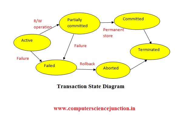
Explanation of each state of a transaction is discussed here
Active State – If we have a set of instructions, until and unless the instructions keep executing, the transaction remains the inactive state.
Failed State – If, while executing instructions, any instruction failure occurs, the transaction will move to failed state (all the instructions must be executed entirely to complete a transaction).
The failed state occurs when the transaction can not be committed, or the transaction is failed during the active state.
Partially Committed State – Once The READ and WRITE Operation Complete, then the transaction becomes partially committed.
Committed State – If the transaction is successful and the updates are also recorded safely, the transaction can move to the committed state.
Failed State – A transaction is partially committed when it has violated Serializability or Integrity Constraints or secondary storage failure for record updation. The transaction has to be aborted, and the transaction will reach failed state.
Aborted State – When all the read/write operations are performed completely, the transaction will move to a partially committed state.
Once a transaction is committed, there is no method to roll back that transaction. The system is also updated in a new consistent state.
Either in the aborted state or a committed state, the system has consistency. The system or process is terminated once the transaction is committed or aborted.
